
Contents
- Patch Antenna - Intro
- Patch Antenna - Various Feeding Techniques
- Patch Antenna - How to design
- Patch Antenna - Measurement
- Patch Antenna - Important of Dielectrics
- Patch Antenna - Multilayer Approach
- Patch Antenna - Patch Sensor
Introduction
A mircrostrip patch antenna in its simplest configuration consists of a radiating patch on one side of a dielectric substrate, which has a ground plane on the side. The patch conductors usually made of copper or gold can be virtually assumed to be of any shape. However, conventional shapes are normally used to simplify analysis and performance prediction. The radiating element and the feed lines are usually photo etched on the dielectric substrate. There are various types of patch antennas using in various applications depends upon their performances. Some basic types are,
- Rectangle
- Square
- Dipole
- Elliptical
- Disc sector
- Ring sector
- Slotted-patch
- Circular
- Triangular
- Circular ring
Advantages
- Low weight and low volume
- Easy to design
- Simple structure to understand the working principle
- Low fabrication cost
- Easy to integrate with microwave circuits
- Normally patch antennas are efficient radiators
- Easy to test under the experimental setup
Rectangular Patch Antenna
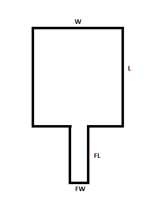
Rectangular patch antenna is a simple type of patch antenna most commonly used for analysing purposes. As per the name this patch has a rectangle shape with a feeder line as per shown in figure. This rectangular patch is placed on a dielectric substrate which has a ground plane below.
Diagram of a Normal rectangular patch antenna
Various Feeding Techniques
- Inset feed
- Aperture feed
- Coaxial feed
- Quarter wavelength feed
- Coupled Feed
Observation
From many source of analysis references, It conclued that inset feed technique provides better performance compared to other feeding techniques.
Inset Feed Technique
Inset feed technique is used to decrease the input impedance of the patch antenna by moving the feeder line into the patch antenna. Patch has higher impedance at the edge can be realized from the given below figure.
Image of Inset Feed Technique in Patch antenna
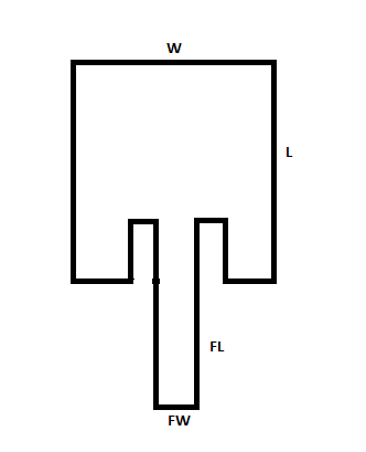
Image of Voltage (V), current (I), impedance (Z) curve along the length of patch
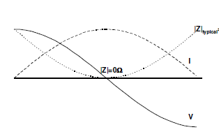
So that moving the feeder line inside the patch will vary the input impedance of the patch antenna as per the equation shows below,
Z(yin) = Z0 * [cos]^2 (πl/yin)
Z (yin) - Input impedance at the length yin
Z0 - Input impedance at the edge
For getting lower input impedance, feeder should be placed in ¼th of the patch length. When yin = l/4,
Z(yin) = Zo / 2
It will reduce the impedance up to 50% of its edge impedance. After this length again impedance will increase as per shown above figure. By this way we can tune the input impedance by changing the inset length. In this project work I have analysed the patch antenna with this inset feed technique which is designed as per above discussed manner.
How To Design
Designing a patch antenna is mainly depends on,
- Resonant frequency (Fr)
- Height of the substrate (h)
- Dielectric constant of the Substrate (ɛ)
Design Equation Document :
A simple online tool to design a patch antenna has been developed in R Shiny environment and available in this Online link and the source code is shared in GitHub as patchdesign_shiny.
Patch Antenna Design - R shiny
Measurement
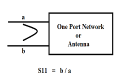
Antenna is a one port device. so only we can calculate S11 parameter. A network analyzer is always used to measure the S parameters in RF circuits. After completing the calibration process with network analyzer, Antenna should be connected to that. In frequency domain, the point in S11 curve at where S11 gets minimum value, that means maximum radiation occurs at antenna is the resonant frequency of the patch antenna.
One Port Reflection Co-efficient
Importance Of Dielectrics
The cavity model equation explains us the importance of this dielectrics in patch antenna. Further explanations and the equations related to the dielectrics attached below.
Multilayer Approach
The multi dielectric cavity is created by adding N number of layers in to a single cavity shown in given below figure.
Single and Multiple dielectric cavities cross section
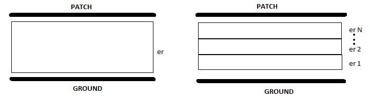
In multiple dielectric cavity has N number of single dielectric cavities with the same magnetic walls of their own cavity and electric walls are varied depends on their places with combination of another dielectric effects. So, each dielectric materials has various dielectric constants and effect of each cavity is accepted by another all cavities.
So what is happening exactly inside the cavity?
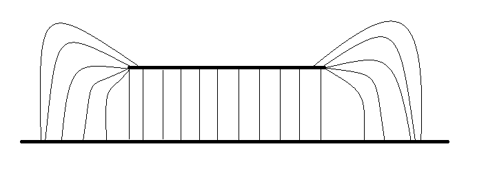
Single layer cavity fringing effect
Multi layer cavity increasing fringing effect
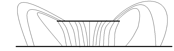
The fringing fields affected by the multiple dielectric materials was theoretically shown and this is called as Fringing effect. Electric fields getting narrower when it crosses higher dielectric constant substrates and ends up with ground plane. In each dielectric the electrical and magnetic components should vary and the field density also vary due to this scenario. The above mentioned cavity model equation states that each cavity resonate in various frequencies and having various electric walls results in complex effects in the antenna. The difference between the dielectric constant that matters for the change in performance.
Equivalent Model For Multi-Layer Cavity
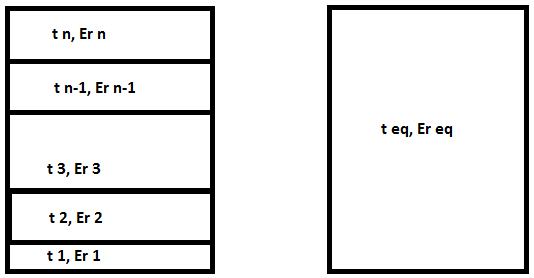
This multi dielectric cavity can be replaced by an equivalent one dielectric cavity without any performance variation derived from references. Above shown figure shows that the equivalent model for multi dielectric cavity.
Further details about the derivation of these equivalent model approach attached in this
This is the equivalent dielectric constant equation for the multiple dielectric layers in a single cavity. The equivalent dielectric constant is depending up on the added dielectric constant and thickness of the material.
Concept of Patch Sensor
From the cavity model resonant frequency equation, we can realize that the relative permittivity of the dielectric is indirectly proportional to resonant frequency. So that multi dielectric layer patch antenna should have shift in the resonant frequency with respect to the equivalent dielectric constant
Resonant frequency vs. dielectric constant curve for a 5.8 GHz patch
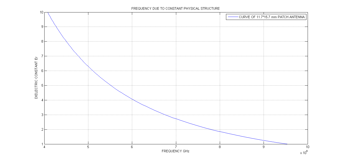
Impact of varying dielectric materials inside the patch on frequency is shown above figure. This curve was get from the 5.8GHz Resonant Frequency patch antenna physical parameters which was designed by dielectric material FR_4 having dielectric constant 4.4. It has relation with the resonant frequency and dielectric constant equations which are discussed above is used to plot the curve. When the cavity is replaced dielectric with lower relative permittivity, the resonant frequency should be shifted to a higher value and vice versa. So that, this curve is used to determine the unknown dielectric constant of a material.
Related Posts
Wireless Transceiver Design Considerations